Timber Columns
Timber Column Analysis
The process of analyzing a timber column goes like this.
- Determine the section properties, in Table 1B of the Supplement, based on the cross sectional size of the column.
- Find out the material properties of the column based on the species, grade, and size of the column by looking in either Table 4A, 4B or 4D.
- You record the adjustment factors for $F_c$ except for $C_P$.
- Use section 3.7.1.2 and Figure 3F to determine the effective lengths $(L_e)$ in both directions.
- Use section 3.7.1.3 of the Timber NDS and calculate the slenderness ratio $(SR = L_e/d)$, for both directions, to determine which on controls.
- Verify that the value of the largest (i.e. controlling) slenderness ratio $(SR)$ is less than 50 (section 3.7.1.4).
- Calculate $F_c^* $ and $F_{cE}$, in section 3.7.1.5 of the Timber NDS.
- Look up the appropriate value for $c$, also in section 3.7.1.5 of the Timber NDS.
- Calculate $\frac{1+(F_{cE}/F_c^* )}{2 c}$.
- Calculate $\frac{F_{cE}/F_c^* }{ c}$.
- Calculate $C_P$, in section 3.7.1.5 of the Timber NDS.
- Multiply $C_P$ by $F_c^* $ to find $F_c'$, the allowable compressive stress parallel to grain.
- Calculate the actual compressive stress parallel to grain of the column.
- Make comparisons between the actual and allowable values.
- Write a summary of your results and conclude if the column is adequate.
In hand solution we will stop and pick a different section if the slenderness ratio $(SR)$ is over 50 rather than doing additional work. You should be aware that in this course I will want you to solve all the values regardless if you find a failure mode early on.
Just so you know, in section 3.7.1.4 you will see that the slenderness ratio is allowed to be up to 75 during construction$^1$. This means prior to putting any axial load on it. By the time the column is loaded the slenderness ratio must be no more than 50.
Let's work through an example to see the whole process.
Footnote 1 - See C3.7.1.4 in NDS.
Problem statement
A No. 2, Southern Pine, 4x6 is being used as a column. The column supports
formwork and is subject to normal temperature and moisture conditions. Bracing
conditions are the same for buckling about the $x$ and $y$ axes.

The axial load on the column is 3.2 kips and the length of the column is 12 ft.
Column Properties
Values from problem statement:
- $\text{Length }=L = 12 ft = 144"$
- $\text{Grade }=\text{ No.2}$
- $\text{Size }=\text{ 4x6}$
- $\text{Axial Load }=P= 3200 lbs$
Values from Table 1B:
- $\text{Thickness }= b = 3 \frac{1}{2}"$
- $\text{Width }= d = 5 \frac{1}{2}"$
- $\text{Cross Sectional Area }=A = 19.25 in^2$
Unmodified Stresses from Tables 4A, 4B, or 4D
Given that the species of the column is Southern Pine, the grade is No.2 and its size is 4x6, what Table should we look up the Unmodified Allowable Stresses in?
- Table 4A (page 32) Reference Design Values for Visually Graded Dimension Lumber (2" - 4" thick)
- Table 4B (page 39) Reference Design Values for Visually Graded Southern Pine Dimension Lumber (2" - 4" thick)
- Table 4D (page 46) Reference Design Values for Visually Graded Timbers (5" x 5" and larger)
(Click on the light blue down arrow to find out what table we need to use.)
Well the beam is $4"$ thick, so we don't use Table 4D; it is for members that are $5" \times 5"$ or larger.
The species is Southern Pine, so than means we use Table 4B of the Supplement.
Table 4B Values (Southern Pine)
On page 39 of the Supplement, under the 2" - 4" Size classification, we find that,
column.unmodified_stresses_latex
Allowable Stress Adjustment Factors
On page 38 of the Supplement there is information about $C_F$, $C_r$, $C_{fu}$, and $C_M$.
- $C_F = 1$ because "Appropriate size adjustment factors have already been incorporated in the tabulated design values for most thicknesses of Southern Pine and Mixed Southern Pine dimension lumber."
- (With the exception of $C_F= 1.1$ for bending members of 4" thick and 8" or larger, but we are not looking at bending and the column is a 4x6.)
- $C_r$ is for bending only.
- $C_{fu}$ is for bending only.
- $C_M = 1$ because the problem statement said "normal temperature and moisture conditions".
If there had been wet service conditions then we would need to find the values for $C_M$ for $F_c$ and $E_{min}$. We would have to further check that $F_c$ was greater than 750 psi to use the $C_M$ value for $F_c$.
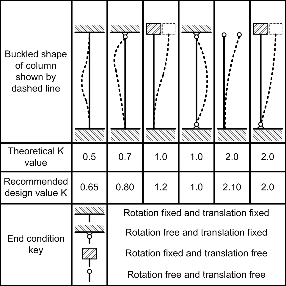
Effective Length
Section 3.7.1.2 in the Timber NDS covers effective length. In it you will see that
$L_e = K_e \times L$

(If you have Thumbnail Zoom Plus or Imagus installed you can hover over the column image to get a better view of it.)
This is the same $K$ as the one that was discussed in the optional lecture on buckling and here. In timber all connections are considered pinned. This is due to the flexibility of both the material and connections. So $K_e$ is always equal to $1$.
I am not saying that $L_e=L$ all the time because we need to account for bracing.
In the column shown to the left (similar to Figure 3F in the 2015 Timber NDS) you will see that the effective length values of the column are measured from midpoint of brace to midpoint of brace. In this case if there were no top and bottom braces it would be measured from end to end for $L_x$ and from end to midpoint of the brace for $L_y$.
Only if no braces are present then $L_e = L$ for both $L_x$ and $L_y$.
Also you should note that the variable for effective length in section 3.7.1.2 is $l_e$ not $L_e$. I'm using $L$ to avoid confusion in hand written assignments where $l$ may look too much like the number $1$. That being said if I inadvertently show lower a lower case $l$ instead of an $L$ you will know why and what it means.
Slenderness Ratio
The slenderness ratio is a measure the buckling resistance of a column in one direction. You calculate it by dividing the effective length (distance between supports, if the column was bending in one direction) by the thickness (or width) of the column in that same direction.
In other words,
- $SR_x = \frac{L_{e, x}}{d}$
- $SR_y = \frac{L_{e, y}}{b}$
In Section 3.7.1.2 of the Timber NDS - Column Stability Factor $C_P$
$$\frac{L_{e,x}}{d} = \frac{144"}{5.5"} = 26.18$$ $$\frac{L_{e,y}}{b} = \frac{144"}{3.5"} = 41.14\text{ }\Leftarrow \text{ Controls}$$ $$SR = 41.14$$(Note that its the largest of these values that controls, and is the slenderness ratio.)
Finding $F_c^* $
$F_c^* $ is found just like $F_c'$ except you don't include the Column Stability Factor $(C_P)$ in the calculation. It is used to take into account that the column could crush rather than buckle. The adjustment values we need to find $F_c'$ are listed in Table 4.3.1 of the Timber NDS. Because the problem statement did not indicate otherwise $C_D = 1.25$ and because there are "normal temperature and moisture conditions", $C_t=1$ and $C_M = 1$. Since the column is Southern Pine, $C_F= 1$. Finally, the column is not incised so $C_i=1$.
$$F_c^* = F_c \times C_D \times C_M \times C_t \times C_F \times C_i $$ $$F_c^* = 1400 psi \times 1.25 \times 1 \times 1 \times 1 \times 1$$ $$F_c^* = 1750 psi$$Finding $E_{min}'$
We also need to know the allowable value for $E_{min}'$ because it is used in the elastic buckling stress equation, $(F_{cE})$.
From Table 4.3.1 we see that we need to know $C_M$, $C_t$, $C_i$, and $C_T$.
- $C_M = 1$ as we just stated.
- $C_t = 1$ as we just stated.
- $C_i= 1$ as we just stated.
- $C_T =1$ because this only applies to truss members that are 2" x 4" or smaller, (section 4.4.2 of the Timber NDS).
column.E_min_latex
Finding $F_{cE}$
$F_{cE}$ is the Elastic buckling capacity of the column (with a factor of safety of 2.75 applied). It is defined in section 3.7.1.5 of the Timber NDS.
$$F_{cE} = \frac{0.822 \times E_{min}'}{(SR)^2} $$$$F_{cE} = \frac{0.822 \times 510,000 psi}{(41.14)^2}$$$$F_{cE} = 247.7 psi$$What is $c$ and Finding $C_P$
The value for $c$ is listed in section 3.7.1.5 of the Timber NDS and it depends on the shape and type of the material the column is made out of. For a sawn lumber column, like a 4x6, $c=0.8$. I'll leave it to you to read about the other possible values.
$$C_P = \frac{1+F_{cE}/F_c^*}{2 \times c} -\sqrt{\left(\frac{1+F_{cE}/F_c^*}{2 \times c}\right)^2-\frac{F_{cE}/F_c^*}{c}}$$Let's find the components of $C_P$ separately.
$$\frac{F_{cE}}{F_c^*} = 0.1415$$ $$\frac{1+F_{cE}/F_c^*}{2 \times c}=\frac{1+0.1415}{2 \times 0.8}=0.7134$$ $$\frac{F_{cE}/F_c^*}{c}=\frac{0.1415}{0.8}=0.1769$$so
$$C_P = 0.7134 -\sqrt{0.7134^2-0.1769} =0.1372$$Allowable Compressive Stress Parallel to Grain $(F_c)$
Because $F_c^* $ is the same as $F_c'$ without $C_P$ being applied we can just find $F_c'$ like this,
$F_c' = F_c^* \times C_P$
$F_c' = 1750 psi \times 0.1372$
$F_c' = 240.0 psi$
or we can find it explicitly.
column.F_c_latex
Actual Stress
To find the actual compressive stress we divide the axial load by the column cross sectional area.
column.f_c_latex
Summary
After an analysis of the No. 2 Southern Pine 4x6, under normal temperature and moisture conditions, and with only end point support, we find that the allowable compressive stress parallel to grain compared with the actual compressive stress is,
column.column_adequacy_check_latex
(Click on the blue right arrow to see the column capacity.)
Column Capacity
That actual capacity of the column is found by multiplying the column's cross sectional area by its allowable compressive stress.
$P_{allowed} = F_c' \times A$
$P_{allowed} = 240.0 psi \times 19.25 in^2$
$P_{allowed} = 4,621 lbs$
References:
Class website (Use this link to if you are taking the course on e-learning.)
Github.io version of course website (Do not use this link if you are taking this course in Summer A or B.)
IPython.org (IPython is the opensource software used in the development of much of this course.)